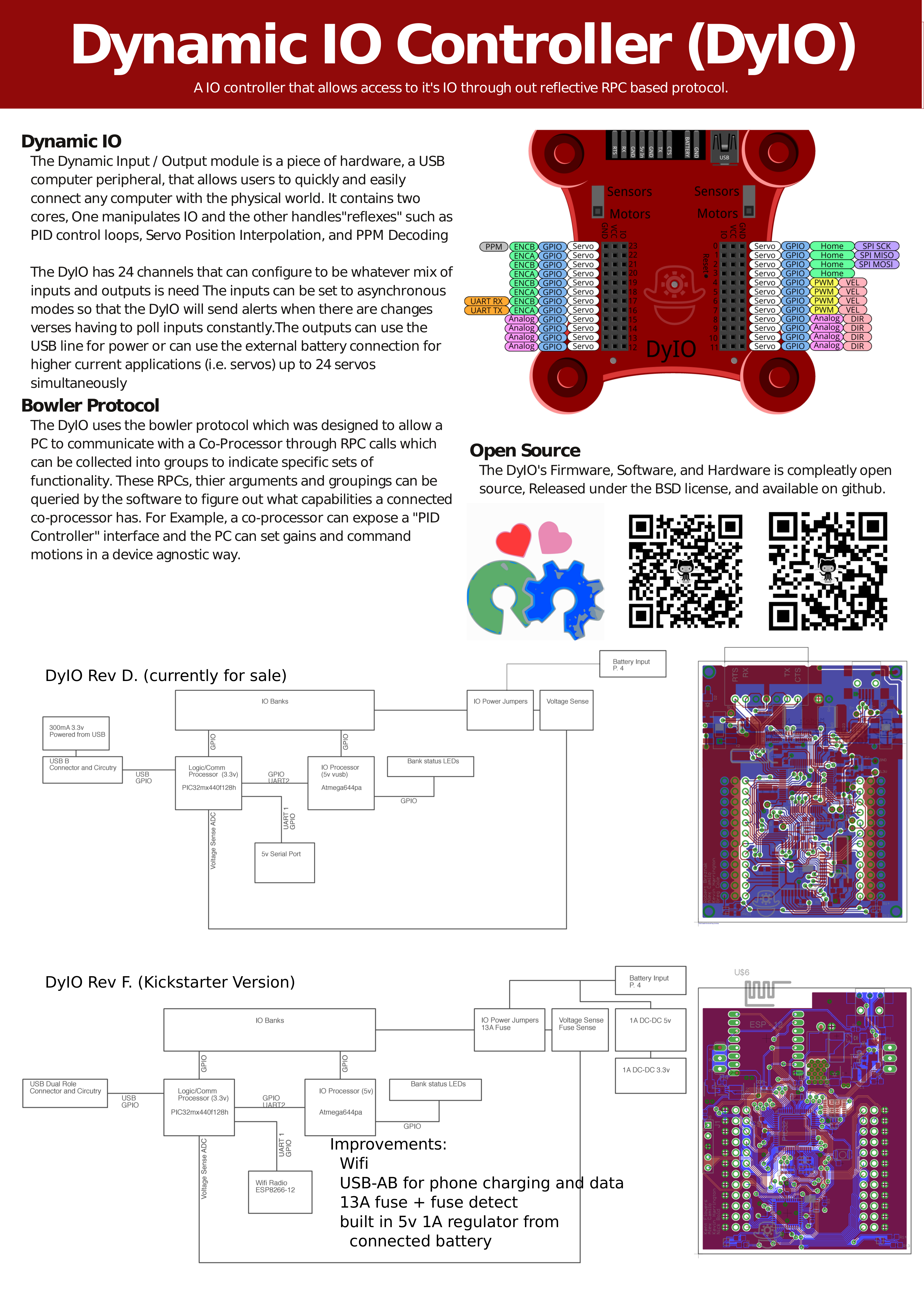
DyIO At a Glance
Starting at the top we see the Bowler Connection which is a 5v level serial port, the External Power Connection which is where you connect an external battery, and the USB Connection where you connect the DyIO to your PC, Phone, or Board.
Moving down we see the bank power Jumpers/Switches which control the power flowing to the banks and the two Channel Banks which is where all your sensors and motors get connected.
Finally, we see the Status LED which shows you what the DyIO is thinking, the Reset Switch which is used for firmware upgrades, and finally the Power Mode LEDs which show you the voltage of each bank’s center row of pins.

Status LED Key:
- Blue: Device is connected to an application and communicating.
- Teal (both Blue and Green): Device is not connected to an application or not communicating.
- Purple (both Blue and Red): Battery voltage fluctuation error (the voltage on a bank set to
- Motors power mode is fluctuating). This is usually caused by the connected battery pack being close to dead or dead, and will update every 10 seconds.
- Red: Error condition. Try re-flashing the firmware or shooting us an email.
- Red to Green slow flashing: Error condition. Try re-flashing the firmware.
Banks and Power
Servos and USB
The DyIO won’t let you run Servoes off of a bank with a Green voltage by default. Computer USB ports are picky and too many servoes could result in damage or odd behavior if powered from USB. If you know what you’re doing then you can disable “Safe Mode” through code or in the DyIO tab to disable this behavior.
Servo Brownouts and Low batteries
The DyIO will Disable Servos if the voltage dips below 5v when trying to move servoes to prevent damage to batteries. You can recover from this by configuring the channel again or commanding another position.
You’ve probably noticed the jumpers or switches above each of the two banks. These connect the banks to either 5v from the PC’s USB port or the connected battery.
The Lights at the bottom of each bank indicate it’s voltage.
- RED indicates Servo/Battery Voltage (5.5 or greater)
- Yellow indicates no voltage
- Green indicates Sensor Voltage (5v)
Moving the Jumper/Switch to the “Sensors” position connects the entire bank to 5v from the USB. Moving the Jumper/Switch to the “Motors” position connects the entire bank to the external Battery.

Inputs and Outputs
The DyIO has 24, 3-pin channels that are grouped into two banks with 12 channels each These channels are used to connect sensors, actuators (i.e. servos) or other peripherals to the DyIO.
Each channel has a number of possible modes that change the behavior of the pin and give the user access to different functionality.